What does a High Voltage Electrician do?

I. Introduction

Electricity is an essential part of our modern lives, powering everything from our homes to our workplaces. However, dealing with high voltage electrical systems can be extremely dangerous, which is why it's essential to have qualified professionals who know how to work with these systems safely and effectively. High voltage electricians play a critical role in ensuring the safety and reliability of electrical systems, making it important to know what they do and how they can help keep us safe.

II. Who is a High Voltage Electrician?

A high voltage electrician is a trained professional who specializes in working with electrical systems that operate at high voltages. These systems typically include power grids, electrical substations, and industrial machinery that require large amounts of electricity to operate. High voltage electricians are responsible for installing, maintaining, testing, and repairing these systems, ensuring that they operate safely and efficiently.

In addition to their technical skills, high voltage electricians must also be highly safety-conscious, as working with high voltage systems can be extremely dangerous if proper safety procedures are not followed. They must be knowledgeable about electrical safety regulations and best practices and must take appropriate precautions to prevent injury to themselves and others.

High voltage electricians may work for utility companies, electrical contractors, manufacturing facilities, or other organizations that require specialized electrical expertise. They may work independently or as part of a team and may be called upon to work in a variety of environments, including outdoor substations, indoor electrical rooms, and other hazardous areas.

Overall, high voltage electricians play a crucial role in ensuring the safety and reliability of electrical systems, making it important to have skilled professionals who are trained and qualified to work with high voltage systems.

III. Job Description and Responsibilities

A. Maintaining High Voltage Electrical Systems

Maintaining high voltage electrical systems is one of the most important responsibilities of a high voltage electrician. This involves regularly inspecting electrical systems to identify any potential problems or areas in need of repair or replacement. Some of the specific tasks involved in maintaining high voltage electrical systems may include:

  1. Inspecting equipment: High voltage electricians must regularly inspect electrical equipment, such as transformers, circuit breakers, and protective relays, to ensure that they are functioning properly.
  2. Testing electrical systems: High voltage electricians use a variety of testing equipment, such as voltmeters and ammeters, to measure the performance of electrical systems and identify any areas that may be in need of repair or replacement.
  3. Cleaning equipment: Regular cleaning of electrical equipment can help prevent corrosion and other types of damage that can affect the performance of the system.
  4. Replacing worn or damaged parts: High voltage electricians must be able to identify when parts of an electrical system have become worn or damaged and need to be replaced. This may involve replacing fuses, circuit breakers, or other components.
  5. https://www.high-endrolex.com/12
  6. Lubricating moving parts: Moving parts of electrical equipment, such as motors and generators, must be properly lubricated to ensure that they operate smoothly and efficiently.

By regularly maintaining high voltage electrical systems, high voltage electricians can help ensure that these systems operate safely and efficiently, minimizing the risk of equipment failure and other potential hazards.

B. Testing Electrical Systems

Another important responsibility of a high voltage electrician is installing and repairing high voltage electrical systems. This may involve working with a variety of different equipment and tools, including cable cutters, conduit benders, and wire strippers. Some of the specific tasks involved in installing and repairing high voltage electrical systems may include:

  1. Reading and interpreting technical diagrams and blueprints: High voltage electricians must be able to read and interpret technical diagrams and blueprints to understand how electrical systems are designed and how they should be installed or repaired.
  2. Installing new electrical systems: High voltage electricians may be responsible for installing new electrical systems, including transformers, circuit breakers, and other equipment. This may involve running conduit, pulling wire, and making connections to existing systems.
  3. Troubleshooting and repairing electrical systems: High voltage electricians must be able to identify and troubleshoot problems with electrical systems and make necessary repairs. This may involve replacing damaged wires, repairing broken connections, or replacing faulty equipment.
  4. Performing system upgrades and modifications: High voltage electricians may be responsible for upgrading or modifying existing electrical systems to meet changing needs or regulations. This may involve installing new equipment, adding capacity to existing systems, or making other modifications to improve system performance.

By installing and repairing high voltage electrical systems, high voltage electricians help ensure that these systems are operating at peak performance and can meet the needs of the organizations that rely on them. This requires a combination of technical expertise, problem-solving skills, and a commitment to safety and quality.

C. Troubleshooting and Repairing Electrical Systems

Ensuring compliance with safety regulations is a critical responsibility of high voltage electricians. Working with high voltage electrical systems can be dangerous, and it is important to follow strict safety guidelines to minimize the risk of injury or damage. Some of the specific tasks involved in ensuring compliance with safety regulations may include:

  1. Staying up-to-date on safety regulations: High voltage electricians must stay up-to-date on the latest safety regulations and best practices related to working with high voltage electrical systems.
  2. Identifying potential hazards: High voltage electricians must be able to identify potential hazards associated with working on electrical systems and take appropriate measures to minimize the risk of injury or damage.
  3. Following proper safety procedures: High voltage electricians must follow strict safety procedures when working on electrical systems. This may include wearing appropriate personal protective equipment, such as gloves and safety glasses, and following proper lockout/tagout procedures.
  4. Conducting safety training: High voltage electricians may be responsible for conducting safety training for other workers who are required to work on or around electrical systems.

By ensuring compliance with safety regulations, high voltage electricians help protect themselves and others from the risks associated with working with high voltage electrical systems. This requires a deep understanding of safety regulations and best practices, as well as a commitment to following these guidelines in all aspects of their work.

D. Designing and Installing High Voltage Electrical Systems

Documenting work and communicating with others are important responsibilities of high voltage electricians. This helps ensure that work is completed according to specifications, that potential problems are identified and addressed promptly, and that others are kept informed about the status of electrical systems. Some of the specific tasks involved in documenting work and communicating with others may include:

  1. Keeping detailed records: High voltage electricians must keep detailed records of all work performed on electrical systems. This may include maintenance logs, repair records, and other documentation.
  2. Communicating with other team members: High voltage electricians must communicate effectively with other team members, such as supervisors, engineers, and other electricians, to ensure that work is coordinated and completed on schedule.
  3. Reporting potential problems: High voltage electricians must report any potential problems or issues with electrical systems to their supervisors or other appropriate personnel.
  4. Providing updates on work progress: High voltage electricians must provide regular updates on the progress of their work to supervisors and other team members.

By documenting work and communicating with others, high voltage electricians help ensure that electrical systems are operating effectively and efficiently. This requires strong communication skills, attention to detail, and a commitment to following established procedures and guidelines.

E. Ensuring Compliance with Safety Regulations

Performing preventive maintenance is an important responsibility of high voltage electricians. Preventive maintenance involves regularly inspecting electrical systems, identifying potential problems, and taking corrective action before those problems lead to downtime or other issues. Some of the specific tasks involved in performing preventive maintenance may include:

  1. Inspecting electrical systems: High voltage electricians must regularly inspect electrical systems to identify potential problems or areas of concern.
  2. Cleaning and servicing equipment: High voltage electricians must clean and service electrical equipment to ensure that it is operating at peak efficiency and to minimize the risk of breakdowns or other issues.
  3. Replacing worn or damaged components: High voltage electricians must replace worn or damaged components, such as fuses, circuit breakers, and other equipment, to prevent potential problems from developing.
  4. Testing and calibrating systems: High voltage electricians must test and calibrate electrical systems to ensure that they are operating within established parameters and to identify any potential issues before they lead to downtime or other problems.

By performing preventive maintenance, high voltage electricians help ensure that electrical systems are operating reliably and efficiently, which helps minimize the risk of downtime or other issues that can impact productivity or safety. This requires a combination of technical expertise, attention to detail, and a commitment to following established maintenance procedures and guidelines.

IV. Education and Training Requirements

To become a high voltage electrician, individuals typically need to complete a combination of education and training. Some of the specific requirements for education and training may include:

  1. High school diploma or equivalent: Most high voltage electrician positions require a high school diploma or equivalent.
  2. Vocational or technical training: Many high voltage electricians receive vocational or technical training through TAFE (Technical and Further Education) or other accredited training providers.
  3. Licensing and certification: High voltage electricians are required to obtain specific licenses or certifications to work on electrical systems. These licenses are issued by state and territory regulatory bodies such as Energy Safe Victoria or WorkSafe Queensland.
  4. Ongoing training and professional development: High voltage electricians must stay up-to-date on the latest industry trends and technologies by participating in ongoing training and professional development programs. This may include attending conferences, workshops, and seminars or completing additional certification courses.

By obtaining the necessary education and training and staying up-to-date on the latest industry trends and technologies, high voltage electricians are better equipped to perform their job duties safely and effectively. This requires a commitment to ongoing learning and professional development, as well as a willingness to follow established guidelines and procedures to ensure the safe and effective operation of electrical systems in accordance with Australian regulations.

V. Skills and Qualities Required

To be successful as a high voltage electrician, individuals need to possess a range of skills and qualities, including:

  1. Technical knowledge: High voltage electricians must have a strong understanding of electrical systems and be familiar with a range of tools, equipment, and technologies used in the field.
  2. Problem-solving skills: High voltage electricians must be able to identify and troubleshoot problems with electrical systems, using their technical knowledge and experience to find effective solutions.
  3. Attention to detail: High voltage electricians must be detail-oriented, able to closely inspect electrical systems and identify even minor issues that could potentially lead to larger problems.
  4. Communication skills: High voltage electricians must be able to communicate effectively with other members of their team, as well as with clients and other stakeholders.
  5. Physical fitness: High voltage electricians must be physically fit and able to perform the physical demands of the job, such as climbing ladders, carrying heavy equipment, and working in confined spaces.
  6. Time management skills: High voltage electricians must be able to manage their time effectively, prioritizing tasks and completing projects within established deadlines.
  7. Adaptability: High voltage electricians must be able to adapt to changing circumstances, such as unexpected issues or changes to project scope.

By possessing these and other skills and qualities, high voltage electricians are better equipped to perform their job duties safely and effectively, ensuring the safe and reliable operation of electrical systems.

VI. Safety Considerations

Working with high voltage electrical systems can be dangerous, and high voltage electricians must take a number of safety precautions to protect themselves and others. Some of the specific safety considerations that high voltage electricians must keep in mind include:

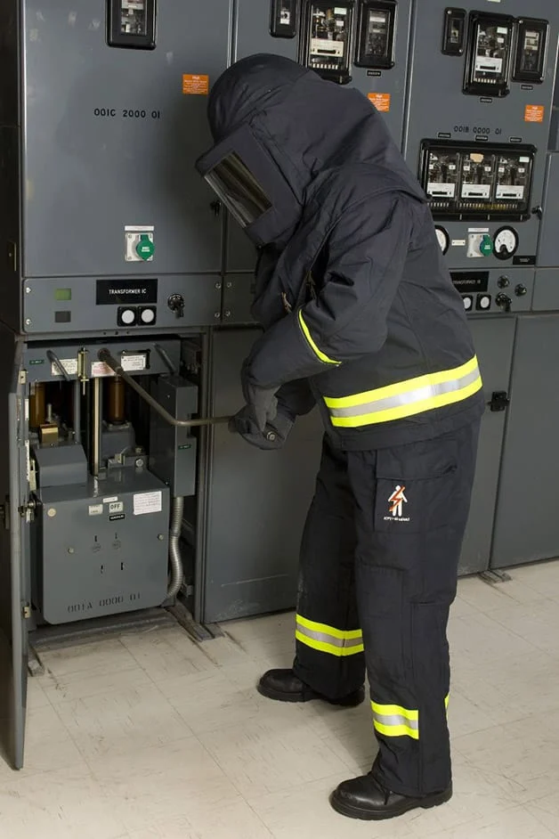
  1. Wearing appropriate personal protective equipment (PPE): High voltage electricians must wear appropriate PPE, such as gloves, safety glasses, and insulated clothing, to protect themselves from electric shock and other hazards.
  2. Following established safety procedures: High voltage electricians must follow established safety procedures and guidelines when working with electrical systems to minimize the risk of injury or death.
  3. Using appropriate tools and equipment: High voltage electricians must use appropriate tools and equipment when working with electrical systems to minimize the risk of accidents or injury.
Why you should perform condition assessments on your HV Cables

When we get calls from clients regarding cable failures there is a general theme that occurs time and time again. “We didn’t realise the cable was in such bad condition” they would say after seeing the destruction caused by the failure. High voltage cables are a common and frequent cause of outages, but how can you determine if they are in good working order? To effectively manage the condition of your cables, owners and operators need to have a good understanding as to the condition of their assets. Eccentricity has over 10 years of experience dealing with high voltage cables throughout a variety of industries and in this article, you will learn how important condition assessments of your HV cables is to ensure the integrity of your electrical system. 

Healthy high voltage cables have evident high-performance characteristics. These include no excess heating, no corona buildup, adequate separation, and correctly utilized installation methods. Many cable failures occur at the point of termination or joint within the electrical circuit. Most of these failures could have been prevented if an effective condition assessment was completed at regular intervals throughout the cable’s lifespan. Ultrasonic and partial discharge (PD) measurements using transient earth voltage techniques is the most effective method for determining the health of your HV cables, however, to get a complete guide to the condition of your cables requires some additional techniques.

It is important to consider appropriate testing techniques for detecting the quality of the insulation and if any partial discharge is present. These techniques offer information that can be gathered through the location of PD activity and assessing the dielectric strength of the insulating medium (insulation quality). 

There are two ways to gather this data for analysis:

  1. Offline Testing:

Offline testing is performed on de-energised circuits using an external power supply such as a very low frequency tester (VLF) which can map any PD present which often contains an in-built tan-delta measurement for assessing dielectric strength. This method can detect aging insulation through the presence of water treeing or insulation impurities. One drawback of this method is that it is time consuming and complex to perform and usually only performed on suspect circuits. 

  1. Online Testing:

Online testing is a great method for determining the condition of your HV cables. It is a non-intrusive method that can be performed on energised circuits by using radio frequency current transformers. These measure the radio frequency current pulses and are generally connected to the earth sheath of the cable. By capturing the waveform data, you can assess the reference signals to determine the level of PD present on the system. 

If performed correctly and at frequent intervals, you can trend the data to predict the condition of your cables more accurately. It is a good idea to complete measurements on newly installed cables also which will provide a good baseline for this trend. With the integration of condition assessments, you can ensure peace of mind that the integrity of your electrical system is maintained and make effective plans to replace cabling nearing the end of its lifespan. 

If you have aged equipment or are suspicious of your cable’s reliability, contact us for support today. 

#highvoltage #highvoltagecables #cablejointer #cablejointing #cablecondition #hvequipment #maintenance #electricalmaintenance #electricaltesting #testingdevice #testing #testingequipment #electricalequipment #electrical #electricalcontractor 

Case Study: 

Why you should perform condition assessments on your HV Cables 1

“Partial discharge detected on existing paper insulated cable due to incorrect installation method and inadequate clearance between phases”

How to Locate Sheath Faults on MV Cables

Maintaining healthy sheath insulation is extremely important for the safe operation and lifespan of an MV cable. If there are faults in the outer sheath you can expect ingress of moisture, debris, and premature degradation of the cables structure. It is difficult to pinpoint the location of the fault as it can occur anywhere along the run of the cable which is usually buried underground. There are however methods to accurately determine the location of the fault which apply a surge energy of around 500J which tests for breakdown and insulation resistance of the outer sheath. 

When Eccentricity come across a sheath fault, we are able to utilize specific test equipment which enables us to locate the fault very easily and accurately. Once the location of the fault has been determined, the cable can be exposed by means of vacuum digging which prevents further damage. It is at this point you can physically see the damage to the outer sheath of the cable. Damage usually occurs due to poor cable laying methods or not enough care taken during installation. 

Rectifying the damage can sometimes be as simple as installing some resin filled zip tube heat shrink which re-seals the outer sheath and re-establishes the insulation resistance. In some circumstances further damage to the under layers of the MV cable can occur and extra repairs such as rectifying termite protection or other protective layers within the cable must be completed. Once the integrity of the cable has been re-established from the repairs it is important to re-test the cable prior to backfill to prove the rectification works. Once verified the cable can be backfilled and tested once again in its final resting position.

Sheath Faults
Image courtesy of EE Publishers.

Have you come across sheath faults on your installation and unsure how to proceed? Give us a call do discuss solutions suitable to your installation.

How to Access High Voltage Equipment Safely

High voltage electrical systems can be extremely dangerous if you do not know what you're doing. Generally, high voltages are only seen in utility services, mining operations, and large industrial processing plants and therefore the dangers are not as well known as you may think. It is important for all workers, not just electrical workers to understand the safety of working in and around high voltage areas. In this article, we outline the common problems and some possible solutions when working in these high-risk environments. 

You are required to understand the exclusion zones associated with high voltage equipment if you are an untrained person. This also includes work performed outside the exclusion zones, where potential may arise for the plant to incidentally contact high voltage equipment. A ‘safety observer’ is required where this is the case to monitor the operator’s movements of the plant or equipment to ensure the exclusion zones are not breached. For specifics for untrained personnel, it is important to understand the associated ‘Code of Practice – Working near overhead or Underground Electric Lines’. 

For trained personnel, the dangers can be managed with the correct implementation of High Voltage Isolation and Access Procedures (HVIA). Once the purpose of the switching operations has been established, E.g/ Access High Voltage Equipment for Repairs, a switching sheet can be designed to suit the installation. The switching sheet is written by a competent and authorized HVIA technician and checked by a supervisor and the switching coordinator for potential errors. This ensures safe switching operations and no details are overlooked that may impinge on the safety of the workers. 

Forward Switching

Once the switching sheet has been approved, the first steps are to isolate, test, and earth the high voltage apparatus that is required to be accessed for works. This process is referred to as the ‘forward switching’ operations. With high voltage equipment not only is it necessary to isolate the equipment from the supply but earthing of the equipment must be implemented to discharge any residual voltages on the apparatus by nearby energized equipment. The safety of the workers is ensured using operator earthing locks and ‘Do Not Operate’ signage placed on the point of isolation. 

Access / Test Permits

The equipment is tested and proved de-energized, and an ‘Access Permit’ is issued to the work crews. The Access Permit Recipient becomes the person in charge of the isolation and all work crews lock onto a lock box that contains the keys from the forward switching operator earth locks. This ensures that equipment cannot be operated until all workers have signed off the permit and removed their locks from the lock box. Once works are completed, a similar permit is issued called a ‘Test Permit’. This permit allows the work crew to verify the works are complete and it is safe to re-energize. Once all permits have been surrendered and canceled the switching operators can commence the re-energization phase. 

Reverse Switching

The re-energization phase of the switching is referred to as the ‘Reverse Switching’. In the reverse switching generally the same process as forward switching is followed but in the opposite order. This ensures all equipment has been returned to ‘as found’ conditions without missing any important steps. It is important to verify supply is restored and any control equipment is operational before leaving site. Sometimes the sudden loss of supply can cause electronic equipment to fail which requires re-setting (usually communications equipment). 

Implementing these HVIA procedures it greatly minimizes the risk of potential hazards present in high voltage equipment and ensures the safety of all associated work groups. If your site has high voltage equipment that you are unsure how to operate safely, we can provide fully qualified and competent personnel to manage your isolations for you.

Oil Sampling & DGA Analysis of Power Transformers

Power transformers are one of the most important pieces of equipment when it comes to electrical distribution. They are responsible for the transformation of higher voltages from distribution to lower voltages as seen in everyday electrical equipment. The most common type of transformer is the oil filled transformer. The internal windings are insulated with paper and the tank filled with an insulating oil. This allows for transformers to be smaller in physical size while maintaining high outputs of power. Many people underestimate the importance of a healthy transformer in relation to the reliability of their power systems. They believe it is a piece of equipment that just sits there and does not do anything as it has no moving parts. While it may look that way from the outside, what is happening on the inside requires special attention.

Dissolved Gas Analysis (DGA) is the study of dissolved gasses in transformer oil. Whenever a transformer undergoes abnormal thermal and electrical stresses, certain gasses are produced due to the decomposition of the transformer oil. By monitoring the content of specific gasses present in the oil you can get a picture as to the condition of the transformer and any history behind abnormal events that may have occurred during its lifespan. This is a non-intrusive method to obtaining a condition assessment of the transformer internals. Generally, the gasses found in transformer oil are Hydrogen (H2), methane (CH4), ethane (C2H6), ethylene (C2H4), acetylene (C2H3), carbon monoxide (CO), carbon dioxide (CO2), nitrogen (N2), and oxygen (O2). 

The oil sample is taken from the sampling point by extraction into 50ml syringes and 500ml bottles. It is important for the sampling containers to be sterilized to ensure the sample does not become contaminated. Generally, it is found that hydrogen and methane are produced in large quantities if the internal temperature of the transformer rises above 150-3000C due to abnormal thermal stresses. If the temperature goes above 3000C ethylene is produced in large quantities. In temperatures above 7000C a large amount of hydrogen and ethylene are produced. Ethylene is a good indicator of hot spots within transformers. If the DGA analysis detects carbon monoxide and carbon dioxide it is presumed there is a decomposition of proper insulation within the transformer.  

The transformer core and windings use paper for their insulation. The paper is made from a cellulose base and its structure is a long chain of molecules. Over time the paper becomes brittle and these long chain molecules begin to shorten. When fully submersed in transformer oil, the lifespan of the paper is severely diminished due to the oxidization that occurs in the oil. When the paper weakens, it cannot contain the mechanical stresses involved with an electrical short circuit. This leads to a breakdown of the paper and therefore it is necessary to monitor the condition of paper insulation inside the transformer. 

Although the DGA test can predict the condition of the paper insulation primarily, it is not a very sensitive method. When the transformer oil soaks into the paper it becomes damaged by heat and some unique oil soluble compounds are released and dissolved into the oil. These compounds belong to the furfuraldehyde group. These furfural family of compounds can only be released from damaged cellulose paper. The furan analysis of the oil is extremely sensitive and damage to even a few grams of paper is noticeable. The percentage rate rise of furfurals in transformer oil over time is used to assess the condition and remaining lifespan of the paper insulation. 

Just by analyzing the dissolved gas and furan content within transformer oil you can get an accurate description and timeline of the internals of the transformer without turning the power off. If your site uses power transformers and does not already perform Oil testing give us a ring to see how we can help. 

The Basics of LV Circuit Breaker Maintenance

It is important to understand the construction and operation of the circuit breaker as they are used in nearly every installation from domestic buildings to high voltage electrical utility substations. They are heavily relied upon to protect our electrical systems when abnormal circumstances arise. With varying shapes, styles, and sizes it is important to understand the correct methods for maintaining this equipment to ensure the safety of people and your assets is not at risk.  

The main type of circuit breakers in low voltage installations are:

MCCB’s are generally smaller in size and have a lower current rating. These circuit breakers are always fixed circuit breakers installed into an electrical switchboard. They consist of the circuit breaker frame, the operating mechanism, an interrupting structure (arc suppression), a trip unit, and terminal connections which connect the MCCB to the circuit’s conductor. Some simpler versions of breakers rely on a thermal magnetic strip for protection whereas others can be adjusted and set via solid state or digital trip units and have much higher interruption ratings. 

ACB’s on the contrary can be quite large and have a much higher current rating. These circuit breakers are usually utilized in heavy industrial situations where large equipment with high load demands such as motors, furnaces etc. are present. These circuit breakers can be of fixed or withdrawable nature and are generally fitted with solid state or digital trip units. 

When performing maintenance in shutdown situations it is imperative to check the components of the circuit breaker for general wear and tear and ensure all electrical components are sound by utilizing electrical tests to verify contacts etc.

1. Circuit Breaker Disconnects and Stabs

The circuit breaker has two main types of disconnects. The main disconnects which connect the main circuit breaker to the bus section of the switchboard and the secondary disconnects which connect the control circuits of the circuit breaker. Visual inspections for any loose connections and low resistance testing verifies the condition of these connections. If any loose connections are found, they are required to be re-torqued to manufacturer specifications. Earthing disconnects can also be found which connects the circuit breaker frame to earth and allows the protection device to operate as quickly as possible in fault conditions.

The Basics of LV Circuit Breaker Maintenance 2

2. Circuit Breaker Contacts

The circuit breaker also has three main types of contacts. Arcing contacts, main contacts, and auxiliary contacts. The arcing contacts are generally constructed of a hardened material such as silver, tungsten, cadmium or zinc which ensures they will not deteriorate as quickly. The arcing contacts make contact first which draws the arc across them preventing the main contacts from drawing the arc which preserves their lifespan. The main contacts of the circuit breaker are generally larger and constructed of a softer more conductive material such as silver. This ensures a low resistance path for high currents to flow. The auxiliary contacts are what connects the control circuits of the circuit breaker. These can provide functions for automatic operation such as operation of motor mechanisms, sending open and close signals to the circuit breaker remotely or monitoring the status of the installation. It is important to inspect these parts for damage and perform electrical tests such as low resistance testing and insulation resistance testing to verify safe operation of the circuit breaker.

Circuit Breakers

3. Arc Chutes

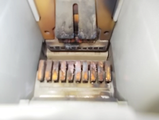
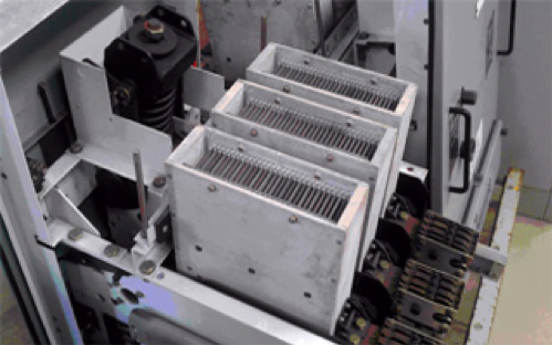
The arc chutes are utilized in the circuit breaker to contain the arc when opening and closing the circuit breaker. It is designed to stretch, cool, and deionize the arc which dissipates into the arc chutes very quickly. They are generally installed right above the arcing and main contacts to draw the arc up and away from the operating parts of the circuit breaker. It is important to inspect and clean the built-up carbon off these chutes during maintenance.

The Basics of LV Circuit Breaker Maintenance 3
Image courtesy of HVUS.

4. Operating Mechanism

The operating mechanism of the circuit breaker is all mechanical and servicing and lubricating of parts is essential. The operating mechanism is often referred to as stored energy as a spring is mechanically charged to ensure the mechanism is a ‘quick make’ and ‘quick break’. This ensures the smallest possible arc is drawn during opening and closing of the contacts. It is particularly important when cleaning and inspecting these parts during maintenance that the springs are fully discharged. This ensures the contacts are unable to be operated while putting your hands inside to clean the contacts.

The Basics of LV Circuit Breaker Maintenance 4
Image courtesy of Liyond.

5. Overcurrent Protection Devices

These devices are extremely important for the protection of the electrical circuit. Most modern circuit breakers have digital trip units and the functions are long-time delay (LTD), short-time delay (STD), instantaneous (INST), and ground fault (GF). It is important to verify the protection device is operating within the manufacturers specified limits. This can be achieved by either primary injection (through the main contacts of the circuit breaker) or secondary injection (through the auxiliary contacts from the current transformers). Trip times of the circuit breaker is recorded which verifies the protection is within the manufacturers tolerance limits.

The Basics of LV Circuit Breaker Maintenance 5

It is imperative to ensure the circuit breakers of your electrical installation are operating correctly for the safety of persons and the safety of your electrical equipment. The consequences of poor electrical maintenance of these devices results in fire, loss of supply, damage to equipment and persons, and loss of business operations. 

Eccentricity recommends a proactive approach to maintenance by scheduling regular energized and de-energized testing into your maintenance protocol. Give us a ring today to see if we can help you manage your electrical assets.

The purpose of the screen and Semi-conductive layer on MV Cables

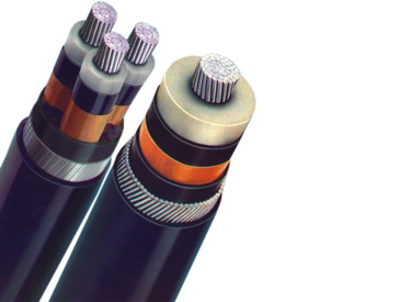
In most modern MV cables, especially underground, cables are shielded, or screened with an earthing conductor. The screen consists of lapped copper tape or metallic foil usually less than 1mm thickness which is the interface between the conductor and the insulation (PVC, XLPE). The main purpose of this conductive screen is to maintain a uniformly divergent electric field and contain the electric field within the cable core. The conductor screen is made from semi-conductive material which is designed to hold back voltage which smooths out the surface irregularities of the conductor by making the voltage on the inside of the insulation the same. This semi-conductive screen material is based on carbon black which is dispersed within a polymer matrix. The concentration of carbon black needs to be sufficient to ensure adequate and consistent conductivity. It must also be optimized to provide a smooth interface between the conducting and insulating components of the cable which is important as it decreases the occurrence of high stress regions on the cable. 

Semiconductive layer on MV Cables
Screen and Semi-conductive layer on MV Cables

The semi-conductive screen also reduces voltage stresses where the conductive components interface with the insulating components. It accomplishes this when the expansion of the insulating layer is typically 10 times greater than that of the conductor so that when the cable is at its maximum operating temperature of 90oC a large enough gap is formed to allow electrical discharges to occur. This then serves to even out the stresses associated with these discharges which would otherwise attack the insulation at specific points along the cable. 

The screen wires are connected at each extremity of the circuit in solidly grounded systems, dispersing the circulating currents of the MV cable. When connecting the screen wires, it is important to note whether the installation is using current transformers (CT’s) for the circuit protection. Any currents on the screen wires will be phasor summed in the conductor by the CT. In the case of fault currents, this is often directly out of phase with the conductor current. As the screen passes through the CT as part of the cable it is then necessary to bring the made-up screen wires back through the CT in the opposite direction prior to grounding. This ensures the screen current is effectively canceled out to ensure the correct operation of circuit protection devices.

How Power Factor Correction Can Save Your Business Money

Does your business spend to much money on electricity?

Power factor correction (PFC) is an often-overlooked component in large electrical installations. It measures how effectively your business uses power. With the majority of businesses within heavy industry having large power costs, todays article will show you how you can minimise these costs while increasing the efficiency of your electrical installation. 

How it works:

By assessing the ratio of real power (kW) to apparent power (kVA). Real power is the amount of power which is actually used by your onsite equipment (kW) whereas apparent power is the total amount of power (kVA) supplied to the site by the utility. A site with a lower power factor draws more apparent power than reactive power, thereby increasing your energy consumption usage. When you have a low power factor the voltage and current supplied becomes out of phase and requires correcting. Low power factor is generally caused by having large inductive loads on site (induction motors, air conditioning compressors, large lighting banks etc). The way in which this is corrected is by creating Reactive Power (kVAR) loads to your installation using capacitor load banks. This helps to correct the imbalance of voltage supplied and current drawn by equipment to become more in-phase with each other resulting in a better ratio of real power to apparent power. 

How Power Factor Correction Can Save Your Business Money 6
https://electrical-engineering-portal.com/beer-mug-and-power-factor

How it benefits your business:

  1. Reduced Demand Charges

If the power factor is low on your site, the percentage of the measured KVA will be significantly greater than the KW demand as mentioned above. Power factor correction will therefore lower the demand charge, helping to reduce your electricity bill.

  1. Increase in load capabilities of existing equipment

When circuits start drawing reactive power from an installed capacitor bank on site such as a PFC it causes a reduction in current flow from an improved power factor and may allow the circuits to carry new loads, saving the cost of upgrades when extra capacity is required. 

  1. Improved voltage

As the line current increases due to a low power factor the voltage drop in the conductor also increases which results in lower voltage supplied to equipment. PFC reduces this voltage drop in the conductor resulting in the correct voltages supplied to equipment. 

  1. Reduction in power losses

System conductor losses are proportional to the current squared (I2). Since the conductor current is reduced due to the power factor improvement, the losses are inversely proportional to the square of the power factor. 

  1. Reduced carbon footprint

By reducing your systems current power demand through PFC, your company puts less strain on the supply grid. Over time this lower demand can account for hundreds of tons of reduced carbon production by utilities. 

If you are looking to increase your power efficiency and cost and have not  yet considered power factor correction on your site, please give us a call for a free assessment and action plan. 

Author: Sam Soady

#powerfactorcorrection

#electricalengineering

#electrician

#highvoltageelectrical

#electricalcontor

#highvoltage

Why Effective Electrical Maintenance Can Save you Money

Unexpected downtime can be an expensive. When an electrical fault occurs, it occurs rapidly, often resulting in major damage to electrical assets. This leaves your business inoperable and vulnerable to the costs associated with downtime and loss of production.  By integrating an effective electrical maintenance program, you can ensure unexpected downtime does not happen. In this article you will understand how that translates into valuable cost savings for your business. 

What is Electrical Maintenance?

It is important to note that the above must be completed by a licensed electrician. 

Why electrical maintenance is important?

How electrical maintenance saves you money

Now that you are aware of the what, why and how of electrical maintenance it is important you speak to a qualified and licenced electrician about your specific electrical installation and what your site requires to operate safely and cost efficiently. For more information it is important to check the QLD Government website  https://www.worksafe.qld.gov.au/ . We are the experts in electrical maintenance and can help you figure out the best program for your business needs. If you want to find out more please visit our website https://www.eccentricity.com.au/services/preventative-maintenance-program/

Sam Soady

#electrician #electrical #electricalmaintenance #highvoltage #electricalengineering

@WorksafeQLD

How to Protect HV Underground Cables

Underground high voltage cables are a great innovation to the electrical distribution industry. While they make an installation look more visually pleasing than the overhead systems currently being utilized, they are often exposed to scenarios which are overlooked by electrical designers and engineers. It is common practice to protect your cables from mechanical damage via installation methods and manufacturing mechanical protection systems, however in some areas, cables have an environmental issue leading to a shortened lifespan and failure. Termites! Even though electrical cables are not considered food for the termites it is well known they can attack underground cables damaging the integrity of the installation, which eventually leads to failures. Some areas in Australia have a higher risk of termites such as the northern part of Queensland and the Northern Territory requiring underground cables to have an added protective layer during manufacturing. 

Methods for termite protection on underground systems include hard physical barriers such as:

  1. Rigid HD PVC Conduit systems.
  2. Added layer of plastic Nylon sheath (must maintain a smooth surface).
  3. Metal barriers such as brass, copper or steel tapes
  4. Chemical infused High Density Polyethylene with Cypermethrin

While all systems are highly effective at providing termite protection the most common method utilized for modern installations is the chemical infused High Density Polyethylene. This solution provides the most cost-effective solution as additional layers are not required to be added to the normal specification/design of the cable. Some companies however have moved away from this method due to Health and Safety concerns which has arisen from the use of these chemicals. 

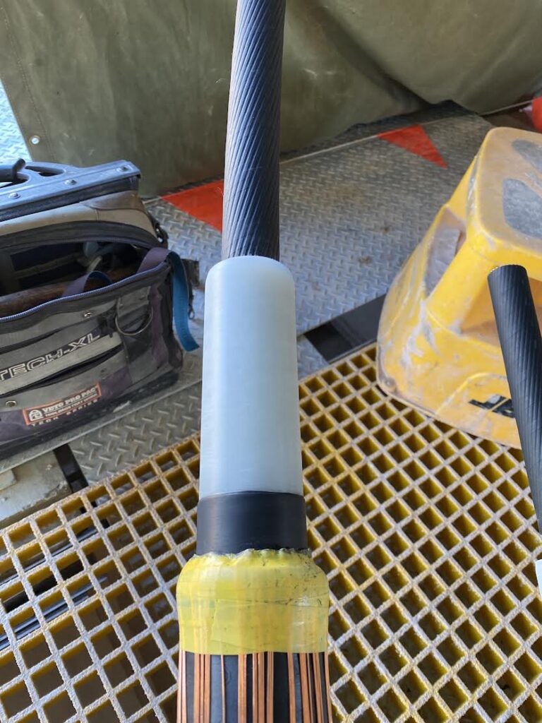
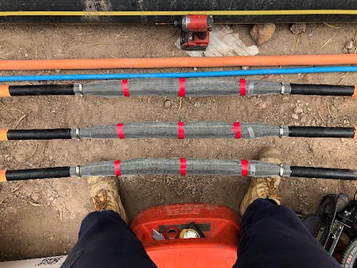
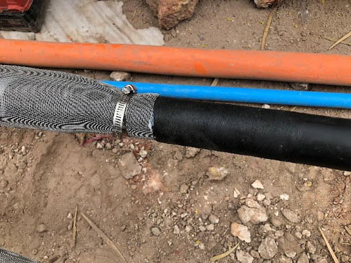
When performing joints/terminations on the cable it is imperative to continue the termite protection all the way through the joint. This is generally achieved using stainless-steel mesh being installed as a protective layer over the joined cable (refer image). The use of roll springs or hose clamps ensures termites cannot enter the joint body.

How to Protect HV Underground Cables 7
How to Protect HV Underground Cables 8

Are you planning on installing underground cables on your electrical systems? Call us today to find out if you require extra protection for your cables.  

Pin It on Pinterest